Creating drawings with Tekla according to GOST, 47 pages, 3 appendices Saimaa University of Applied Sciences, Lappeenranta. The purpose of the thesis was to study the possibility of creating drawings with Tekla Structures in accordance with Russian standards, to study what can be changed and what has already been changed. The thesis should be of interest to designers engaged in 3D modeling and to designers who will start working with 3D software in Russia and in accordance with GOSTs.
The first part of the thesis contains the description of current Russian standards, their history and development prospects, general information about Tekla Structures, its use in the world and in Russia, information about the development of the Russian environment in FMC . It also describes the general programming technology in Tekla and the improvements made: table changes, creating the templates. The last part describes the process of handing out the drawings, exporting to DWG and printing from Tekla Structures.
INTRODUCTION
ACTUAL RUSSIAN NORMS
GOST standards were originally developed by the government of the Soviet Union as part of its national standardization strategy. After the disintegration of the USSR, the GOST standards acquired a new status of the regional standards. The task of harmonizing Russia's standards and the GOST standards was set in 1990 by the Soviet Council of Ministers at the beginning of the transition to a market economy.
Thus, GOST standards are used in all CIS countries, including Russia, while GOST R standards are valid only on the territory of the Russian Federation. This standard specifies the composition and rules for architectural working drawings of buildings and structures; used since September 1, 1994 as an official standard of the Russian Federation. This standard specifies requirements for performance specifications for equipment, products and materials for the basic set of working drawings of buildings and structures of various purposes; used since July 1, 1995 as an official standard of the Russian Federation.
TEKLA STRUCTURES
General information
- Using Tekla in the world
- Using Tekla in Russia
This standard specifies the basic requirements for the design documentation for capital construction and work documentation of all types of construction projects. The Russian system of regulatory documents is at the stage of renewal of Soviet standardization. Tekla Structures (TS) is Building Information Modeling (BIM) software that enables the creation and management of accurately detailed, highly constructable 3D structural models, regardless of material or structural complexity.
The entries for the Global BIM Awards competition are the winners of local Tekla BIM Awards organized by Tekla area offices and resellers worldwide. This means that it is not only used to obtain finished drawings, but also for other parts of the life cycle of the building. And they usually use TS for the internal purposes, for example: the drawings of the details to send to the factory.
Development of the FMC Tekla Russian Environment
- Past of the FMC Tekla Russian Environment
- Tekla FMC-Russian Environment nowadays
- Tekla FMC-Russian Environment and planes for future
Many huge buildings were created with Tekla in the world, and many smaller projects are carried out every day. They are in no hurry to integrate this software, because there are no regulations for its use in Russia. Today, the process of improving FMC-Russia is still one of the most important topics for Finnmap.
The main principle of this process is to make improvements during the creation of the project. Here is one interesting point: Steel profile catalog is created in the following way: Letter is changed into profile symbol Figure in drawing layout with special font. It is possible to improve symbols catalog during the project, especially for special diameters.
COMPARISON WITH THE STANDARDS
- Databases
- Templates
- Tables
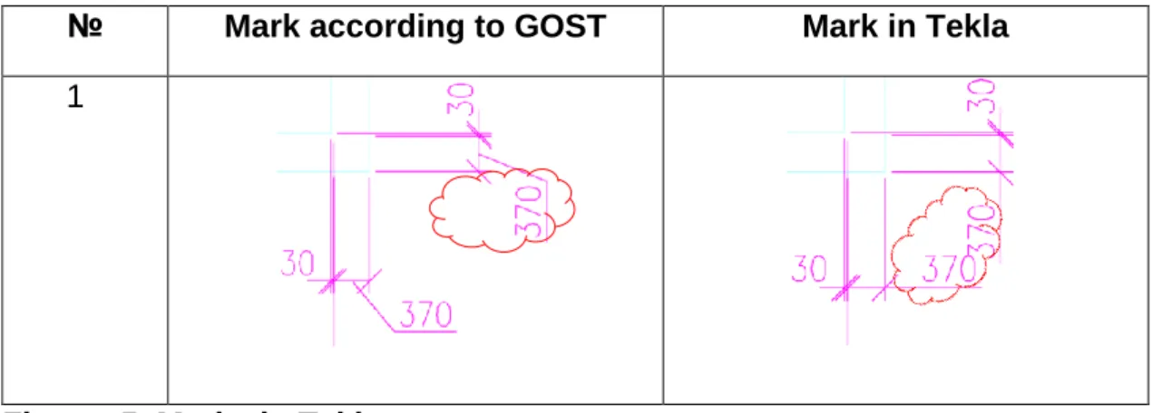
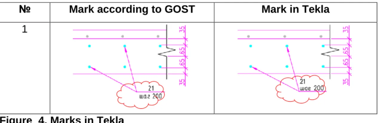
- Marks
- Dimensions
- Texts
Templates are used for various purposes, for example to print a list of parts used in a construction, to indicate the legend on an electrical network map, or to provide statistics about the content of the map, such as city area, scale or date. Therefore, a comparison has been made of the tables embedded in Russian Tekla with Russian standards. During the study of the environment, many gaps were found in the design of the tables.
In some cases, it is not possible to create the required table format with TplEd at all. It is possible to select different types of tags, view and change settings that affect the appearance of the tag in the Tag Properties dialog box. However, it is still not possible to change the location of the text and put it under the line.
IMPROVEMENTS MADE
General technology of programming in Tekla
The forms can be graphical for inclusion in drawings as tables, text blocks, drawing headings, or ASCII text forms for reports. They are primarily used to create reports or lists of application area-specific objects, for example in bill of materials of steel structure constructions in Tekla Structures. Although TplEd lets you use different fonts and settings, they do not appear in the output template.
When you revise the model, Tekla Structures also updates the drawings, so they are always up to date. A master drawing is a Tekla Structures drawing or a set of drawing properties used to create new drawings that look the same as the master. Drawings in the Master Drawing Catalog with a ruleset, Tekla Structures uses the properties defined for the saved settings file or clone template used in the ruleset.
Drawings in the main drawing catalog with saved settings Tekla Structures uses the properties specified in the saved settings file you select. Drawings in the main drawing catalog with clone templates Tekla Structures creates a drawing using the properties that were defined for the drawing used as the clone template, along with any manual changes you made to the clone template. Drawings with the Drawings and Reports menu commands, Tekla Structures uses the current properties in the corresponding drawing properties dialog specific to the drawing type.
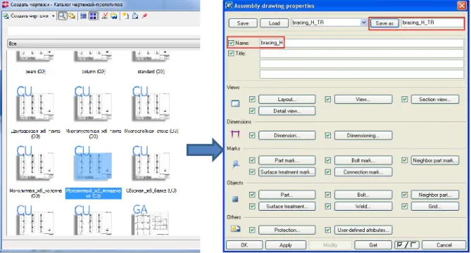
The current properties in the drawing properties dialog box are also used when drawings are created using toolbar command buttons or popup menu commands. The settings stored in the Master Drawing Catalog (Figure 6) are drawing properties files that are created and stored in the drawing properties dialog boxes for different drawing types. There are many default drawing properties files, and you can also create your own in the drawing properties dialog boxes (Figure 7).
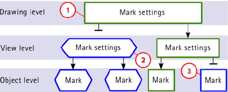
1 The color and shape of the border for the entire drawing can be changed at the drawing level.
Action plan
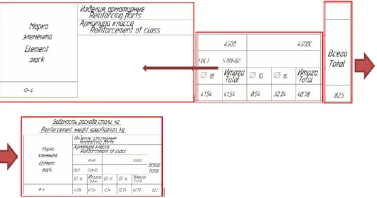
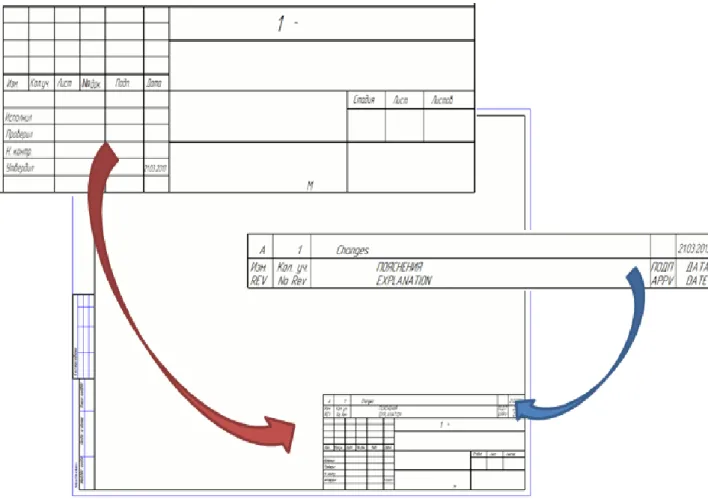
It is convenient to create a new layout and add tables needed for the specific type of drawing. Stamp for the main set of working drawings, graphic documents of design documentation, graphic documents for Engineering survey. One of the basic tables has been modified for the calculation of special detail on the drawing, for example ventilation blocks.
Show Openings/Cuts Symbol: Yes (In file XS_USE_CROSS_FOR_OPENING_SYMBOL in Advanced Options Advanced Options Reference Guide. Later in the drawing line the main detail type will be changed to solid.
The trial model of block of flats
- Dimensional layout drawing
- Layout of columns and walls
- Pillar reinforcement drawing
The first drawing created of the model is dimensional layout of plate at level +3.600. The General Arrangement drawing template was used for drawing the dimensional layout of plate. But it is important to remember which part of the structure will be visible and which will be hidden.
Part of this wall will be visible and the rest hidden in the top plate dimensional layout drawing. All these templates are combined in the object-level settings window and connected to the following part filters (Figure 21). Hole marks must include the type of hole (BK, OB, ЭО) and its size.
It is recommended to delete the cutting part, but the intention is to leave it and use it to get the dimensions of the hole. The next step is to select characteristics from the list of elements in the part label dialog. Profile - adds the name of the work profile (width and height); size - adds the size of the part (width and height); length - adds the length of the part.
If you leave the cut, you can dimension it - but it still doesn't work correctly, because it only dimension the reference (center) points of the part - not the actual part. The variable XS_USE_CROSS_FOR_OPENING_SYMBOL is responsible for the type of symbol in openings and recesses. In this drawing, the dimensions of the holes and their attachment to the axis were hand-made.
The number of the reinforcement bar can be displayed on the drawing in the symbols from the SERIAL_NUMBER attribute.

GIVING OUT THE DRAWINGS
Exporting to DWG/DXF format
It keeps settings for transformation with the drawing for the new format, line type, line weight and color. Layers common to Finnmap are also created in the Drawing Export Layers dialog box. It is important to note that the hole marks created for cutting parts refer to the object group details, and the hole marks created without snapping to the detail refer to the object group text.
The LineTypeMapping.xml file is supposed to define the linetype, weight, and color for different layers. The font conversion file defines which font file will be associated with the created AutoCAD style and optional font width and height correction factors.
Printing with TS
Today, Tekla Structures is part of a large software complex based on building information modeling (BIM). It has great potential for engineers; can increase the speed of the work process very effectively. The main problem of its use in Russia is the lack of opportunities to make drawings in accordance with the norms.
Otherwise, the effective use of TS in Russia will be impossible due to the large amount of manual work. The drawing can be made entirely in Tekla without modifications in other programs such as. Setting dimensions and marks is difficult for complex reinforcement objects and cannot be done automatically.
In conclusion, regarding the development prospects of TS in Russia, as said, the Russian market is one of the most underdeveloped regions of Tekla users. So Tekla Company should certainly continue product development in the Russian market and pay.
Russian projects carried out in Tekla Structures
COMPARISON OF THE TEKLA AND GOST
Dimensional Layout of slab
Плита на отметке+3600 Плита на отметке+3600 Плита на отметке+3600 Плита на отметке+3600 +3600 Примечания: 1. Обработать поверхности стыков, перед заливкой обработать согласно